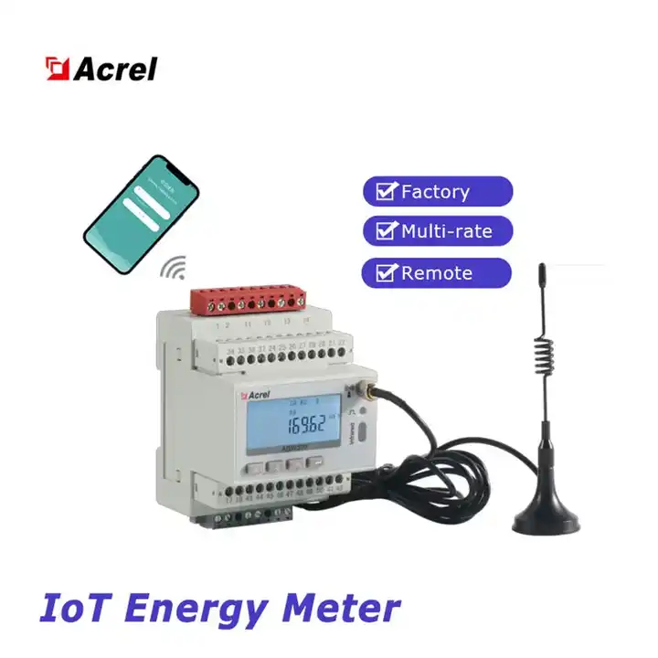
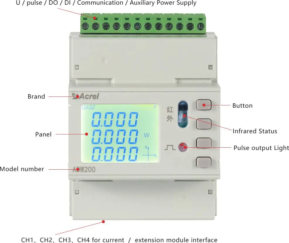
ADW210 IoT Wireless Multi-function Smart Energy Meter
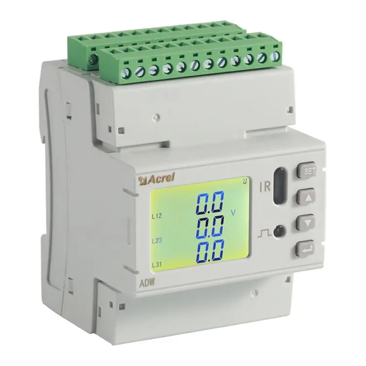

Characteristic
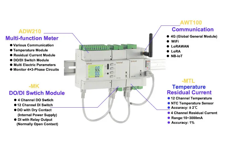
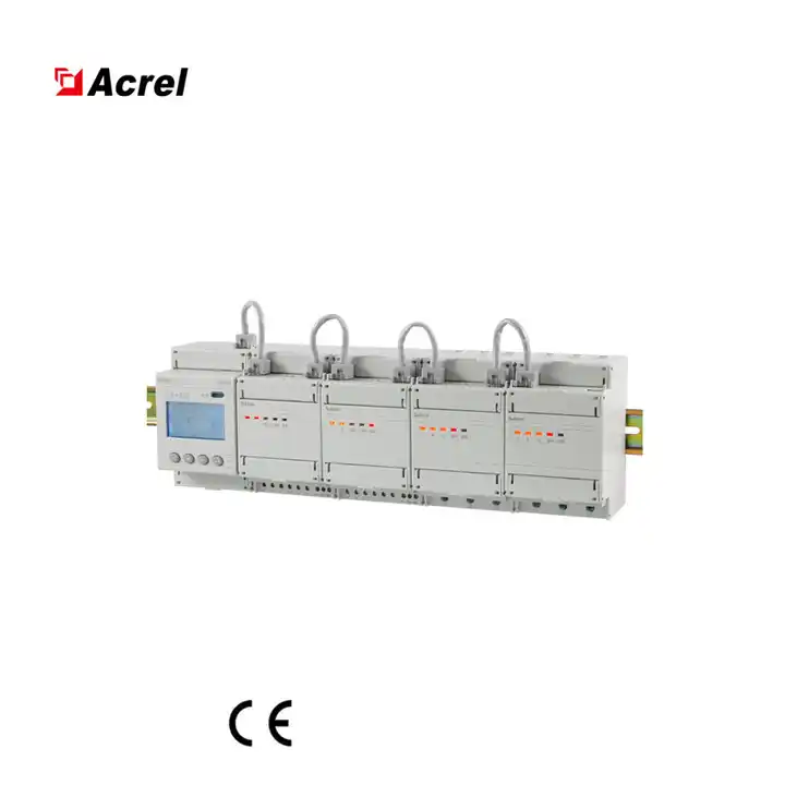
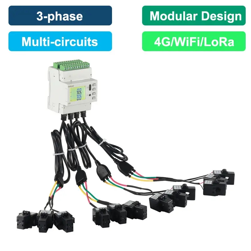
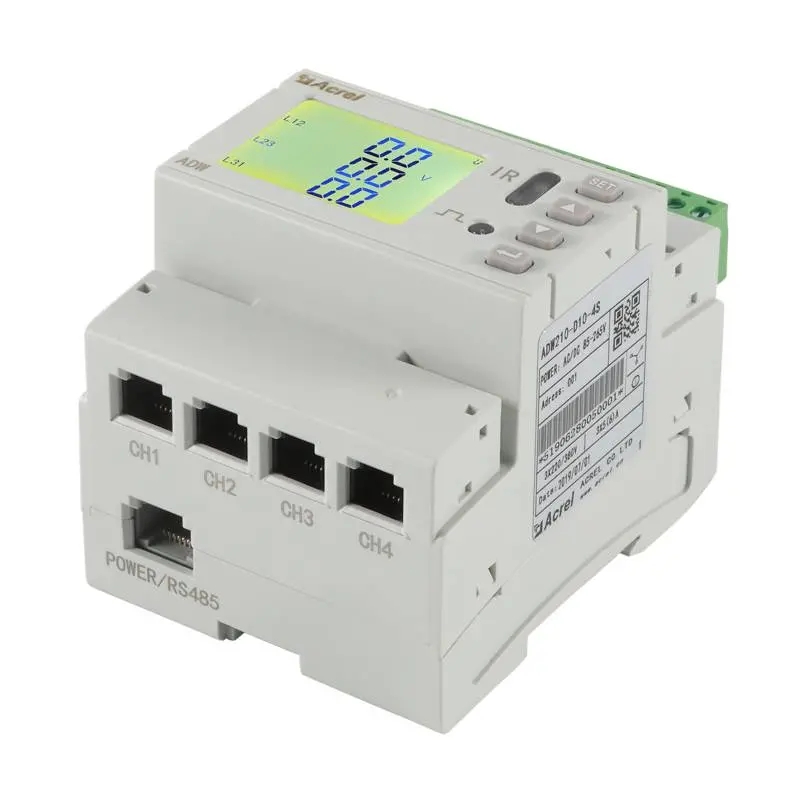
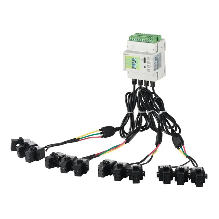
Multi-circuits Monitoring
● Monitor up to 4×3-phase circuits in total
● Paired CTs with specs of 5A/1.25mA; 100A/20mA; 400A/100mA or 600A/100mA
● External CTs Connectwith ADW210 Main Body thrrough RJ12 Interface
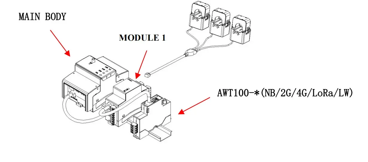
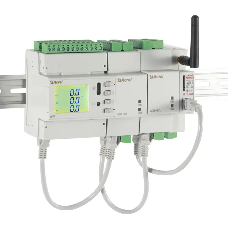
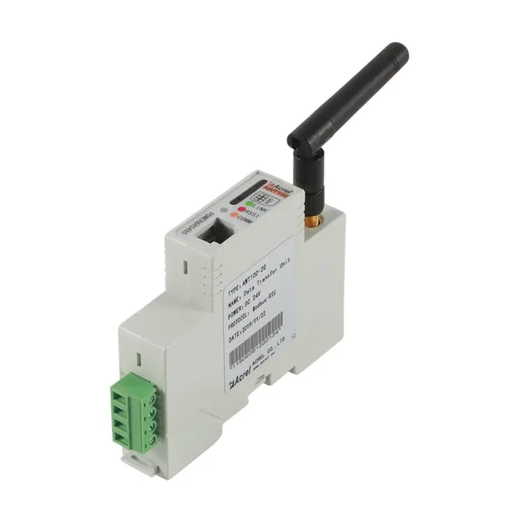
Expanded Communication Module --- AWT100
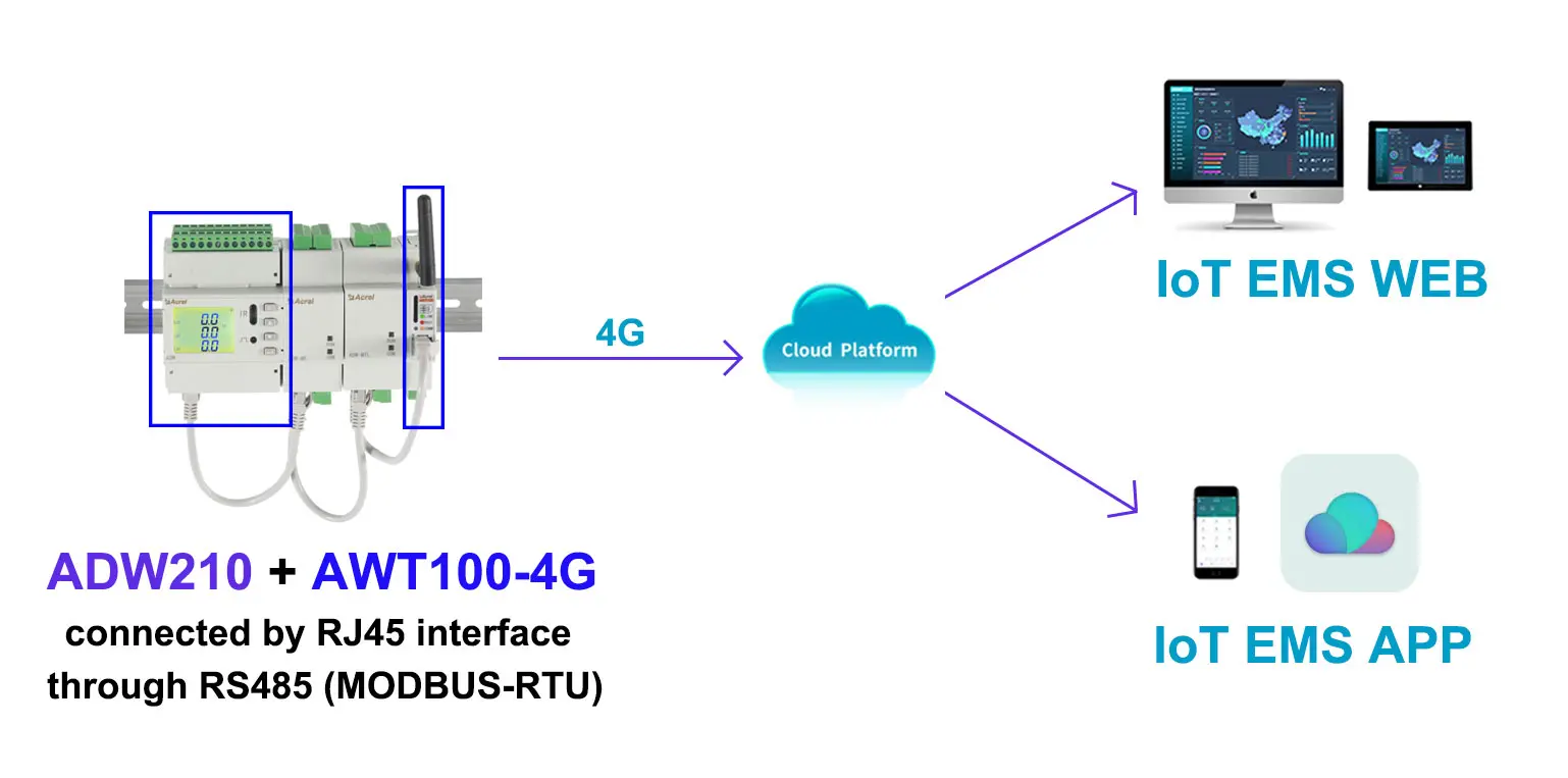
● 4G (Global general module)
● WiFi
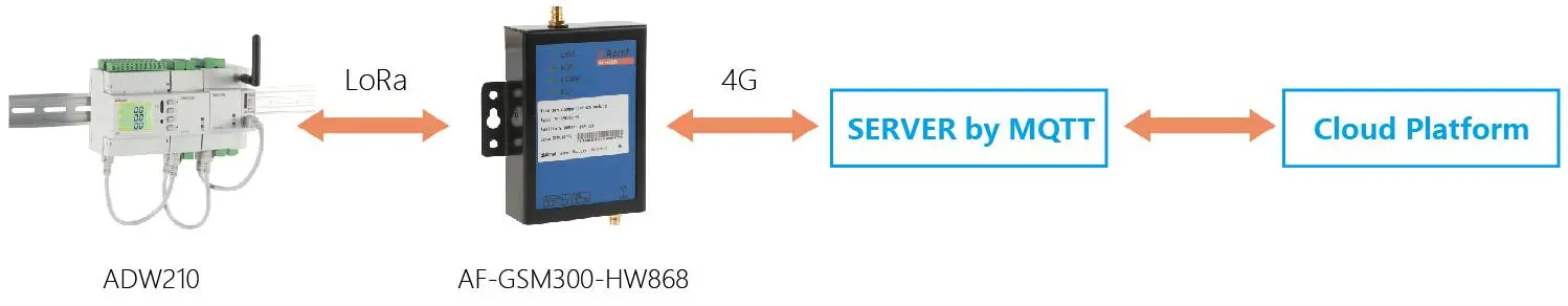
● LoRaWAN
● LoRa
● NB-IoT
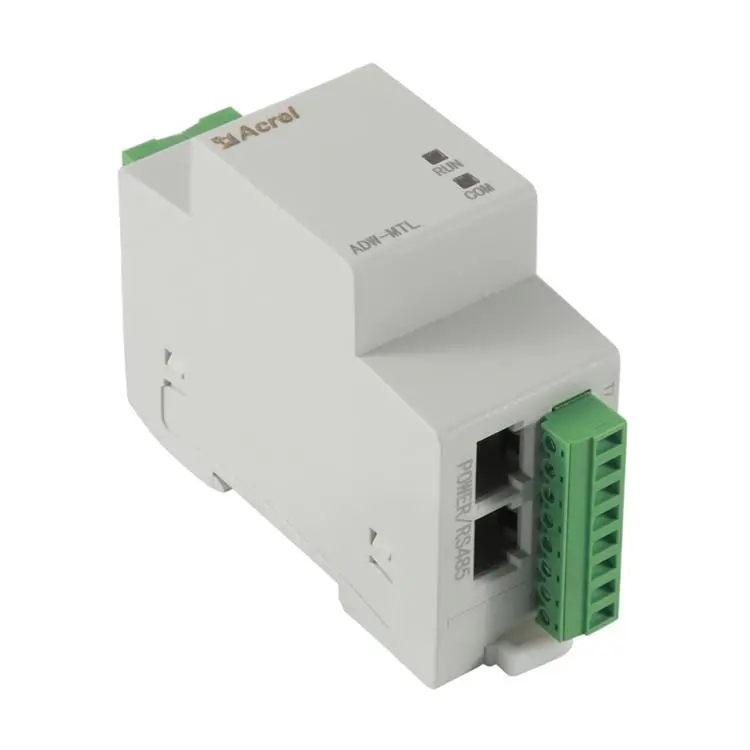
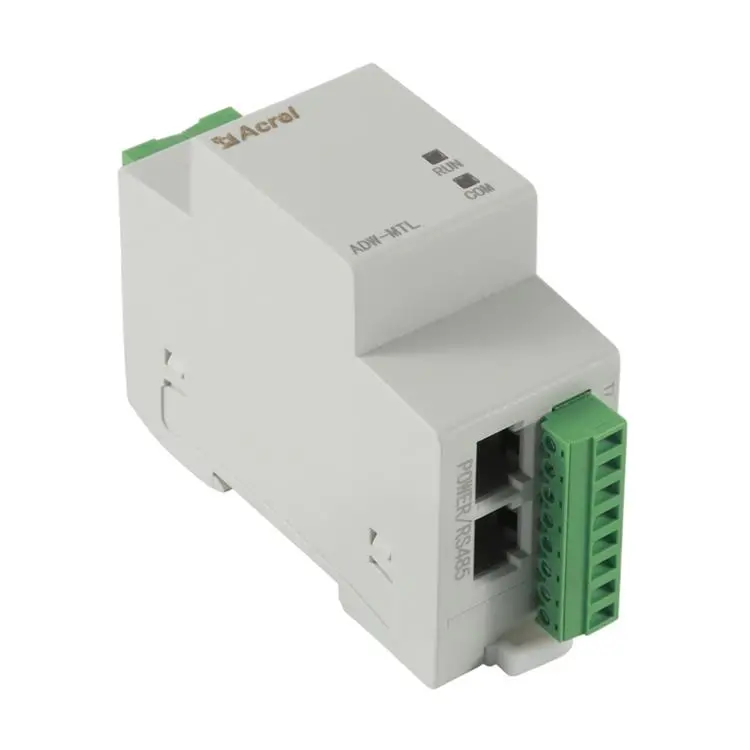
Cable Temperature&Residual Current Measurement Module --- MTL
● Temperature Measurement:-20℃~+100℃
● Residual Current Measurement:10~3000 mA
● Accuracy:Temperature:± 2℃; Residual Current:1% (Class 1)
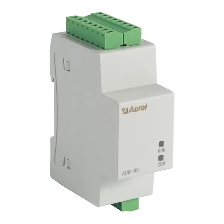
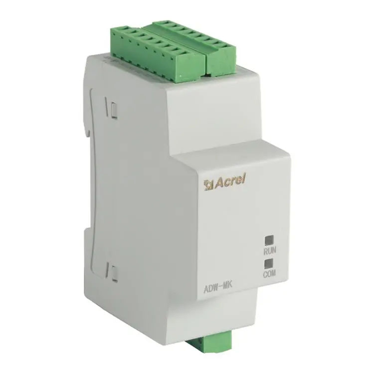
DO/DI Switch Extra Function Module --- MK
● 12 channel DI (Digital Input)
● 4 channel DO (Digital Output)
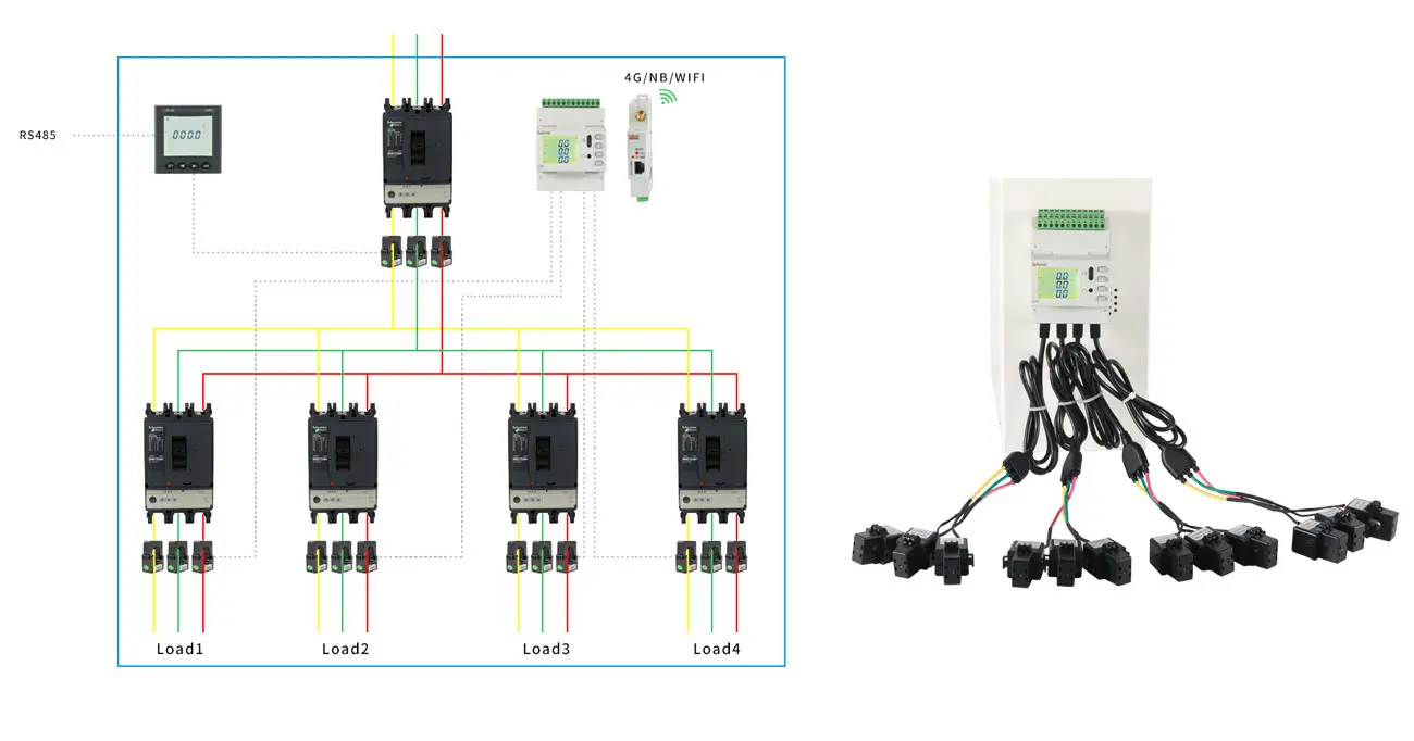
3-phase 4-wire Wiring of ADW210 monitoring 4 3-phase Circuits

Wiring between ADW210 Main Body and MTL&MK Extra Function Module through RJ45 Interface
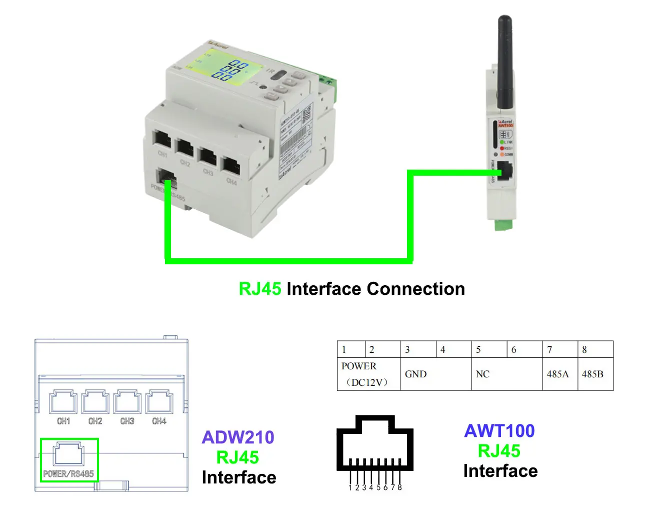
Wiring between 1 ADW210 Main Body and 1 AWT100 Communication Module
(Attention: In the connection between 1 ADW210 and 1 AWT100 through RJ45 interface, we don't need Auxiliary Power Supply for AWT100)
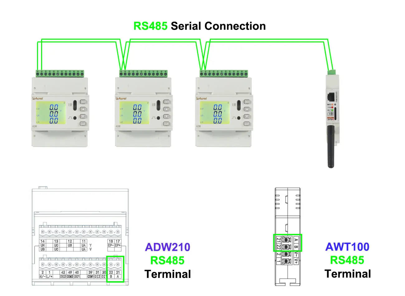
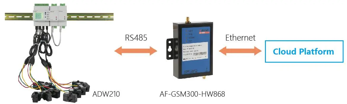
Wiring between more than 1 ADW210 Main Bodies and 1 AWT100 Communication Module
(Attention: In the connection between more than 1 ADW210 and 1 AWT100 through RS485 Serial Ports, we need DC24 or DC12V Auxiliary Power Supply for AWT100)